
A magnetic separator for tire recycling removes steel only after the wire can move independently from the rubber around it. Upstream size reduction and rasping expose the steel; the magnetic stage then changes the trajectory of that ferrous material so it leaves the rubber stream through a different discharge. When wire still appears in the product, the cause may be incomplete liberation, a deep or uneven burden, excessive working distance, too little capture time, tangled wire at the discharge, or steelwork around the conveyor interfering with the intended magnetic path.
Can a Magnet Pull Steel Wire Out of Rubber?
Not reliably when the wire is still locked inside a thick rubber block. Magnetic attraction acts on the steel, but the surrounding rubber adds mass, friction and mechanical restraint. A free steel strand and a rubber-steel composite may contain the same steel, yet one can move toward the magnet while the other remains trapped in the rubber stream.
This gives the operator a very useful first test: inspect material immediately before the magnetic zone. If the remaining steel is still embedded in large rubber pieces, the first problem is not the magnet. If the steel is already free and still appears in the rubber after the separator, magnetic capture and material presentation become the next suspects.
Where Magnetic Separation Fits in the Tire Recycling Process
YUXI’s tire wire steel separation system places magnetic separation after shredding and preliminary steel-wire separation. The current solution lists the tire shredder and tire rasper as its main machines, followed by magnetic separation and purification.
The sequence matters. The tire rasper working principle explains the upstream liberation duty: reduce the rubber and expose embedded steel. Magnetic separation begins after that physical bond has been weakened enough for the wire to respond independently.
There are also several magnetic duties that should not be confused. The first is bulk recovery of liberated steel after rasping. A second possible duty is cleaning rubber still trapped in the recovered-wire fraction. Later, after the rubber has been reduced further, a polishing stage may remove smaller residual ferrous pieces at much lower metal loading.
This article concentrates on bulk steel recovery. Detailed multi-stage magnetic architecture belongs to a separate system-design topic.
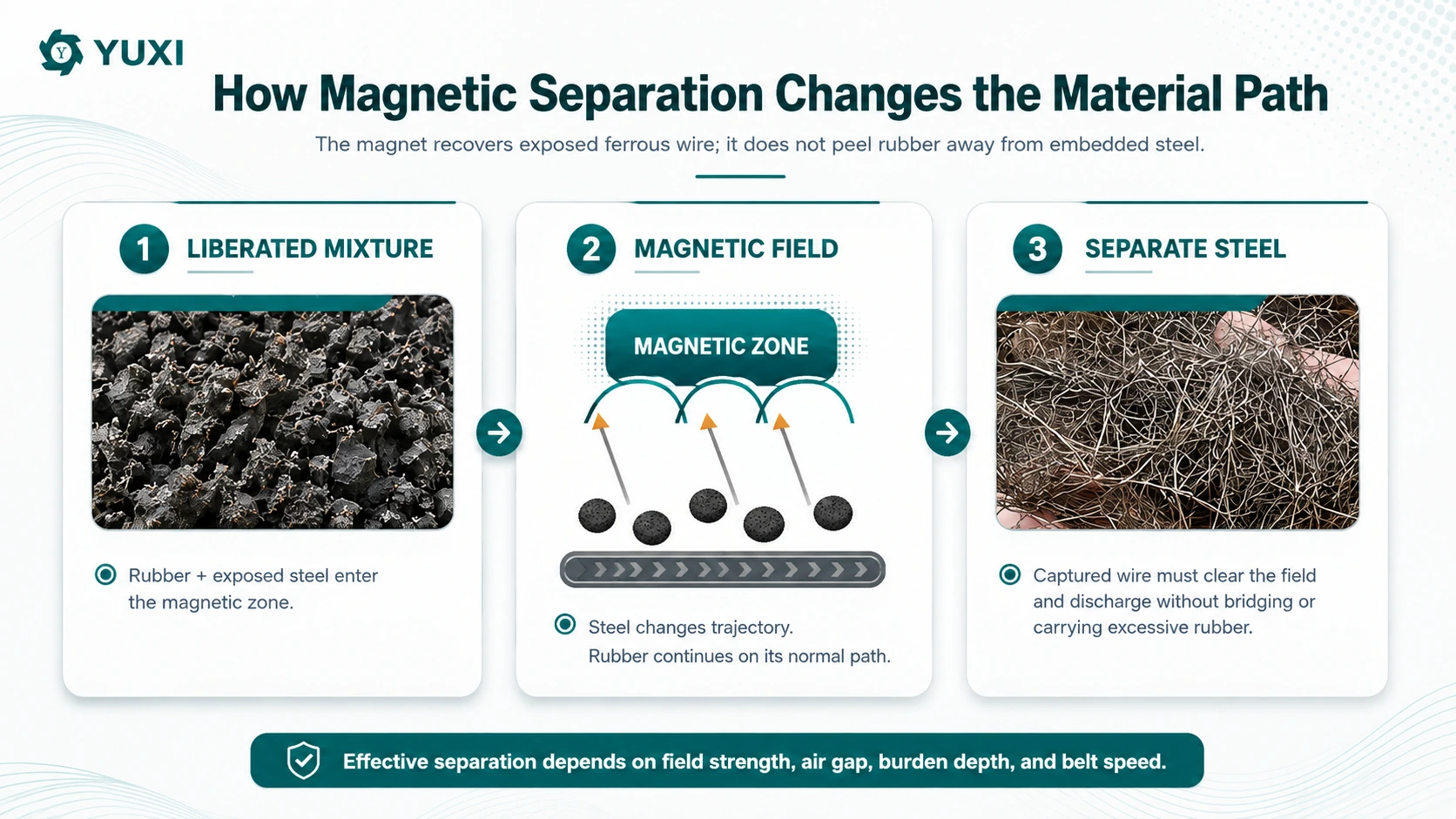
How the Magnetic Stage Changes the Steel Trajectory
In a suspended or overband arrangement, the magnetic field reaches down toward the conveyed material. Liberated steel is attracted upward, must escape the rubber burden, reach the separator belt or magnetic face, and then travel to a separate steel discharge.
A drum or magnetic-pulley arrangement creates a different path. Ferrous material stays attracted to the magnetic surface for longer while non-magnetic rubber releases earlier. In both cases, separation succeeds only when steel and rubber follow sufficiently different trajectories before they leave the useful magnetic zone.
This is more precise than saying “a strong magnet attracts the wire.” The useful force acts at the steel’s actual position, not at the magnet surface. Both the field at that position and how the field changes through space contribute to the force available to move the steel. A surface Gauss number by itself therefore cannot describe the complete separation condition of a buried tire-wire strand.
Material presentation can also help or hurt. Magnetic pulley systems that agitate or tumble the material can expose entrapped ferrous pieces differently from a static deep burden. The point is not that one separator type is universally better; it is that the steel must be allowed to move relative to the rubber.
Working Distance: Air Gap and Burden Depth Act Together
For an overband separator, the visible clearance above the conveyor is only part of the working distance. A wire near the bottom of the burden is also separated from the magnetic source by the rubber above it, the conveyor belt and any protective layer between the product and the magnetic source.
As the steel gets farther from the magnetic source, the useful magnetic action available at that point falls. That is why a separator can perform differently even though its electrical or permanent-magnet system has not changed.
Burden depth changes continuously in a real plant. A conveyor may look lightly loaded on average but receive short, deep piles whenever the upstream machine discharges a surge. Wire near the top of that pile and wire close to the belt do not experience the same recovery condition.
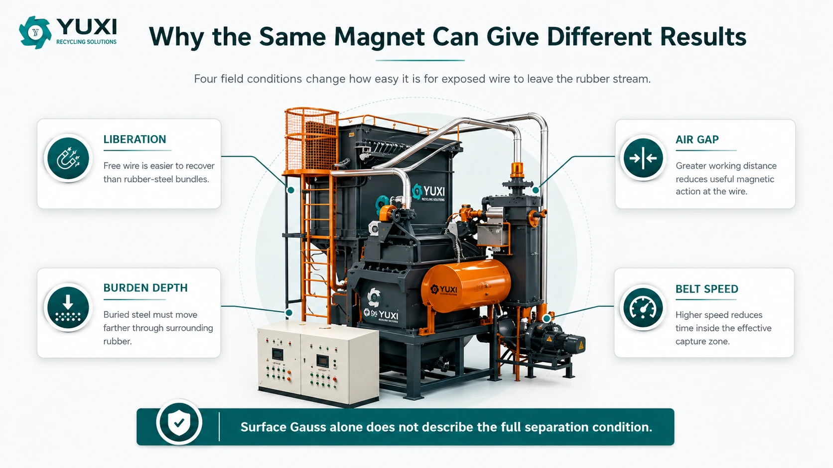
Watch the burden profile across the belt width, not only the total feed rate. A narrow rope of material can create one deep column under part of the magnet while the rest of the separator width is lightly used. If missed wire appears mainly in that local peak, the feed presentation is part of the problem.
Lowering an overband magnet reduces the working distance, but the highest normal burden and the lifted tire wire still need physical clearance. Material buildup on the magnet cover or separator belt can create an unintended extra gap as well. A gradual decline in recovery can therefore be mechanical accumulation rather than loss of magnetic strength.
Belt Speed Controls the Available Capture Time
A wire only spends a limited time inside the useful magnetic field. Higher conveyor speed shortens that time. If higher throughput also deepens the burden, the same production increase can make the wire both harder to reach and quicker to leave the capture zone.
Slower is not automatically better. Excessively slow conveying can create accumulation, starve downstream equipment or move the bottleneck elsewhere. The target is a repeatable combination of belt speed, feed distribution and burden depth that maintains the required rubber and steel outputs.
During troubleshooting, change one major variable at a time. If feed rate, belt speed and separator height are all changed together, a cleaner result gives no reliable evidence about which variable corrected the failure.
The time pattern itself is useful evidence. A line that works immediately after startup but degrades after normal wire buildup has developed is telling you something different from a line that misses wire only during feed surges. Treat those patterns as diagnostic observations rather than averaging them into one overall production number.
Long Tire Wire Must Be Captured, Carried and Discharged Cleanly
Liberated tire steel is long, flexible and prone to tangling. Free steel may arrive as individual strands, short fragments or large intertwined bundles. Those shapes do not behave the same way.
A tangled bundle can respond strongly to the magnet while mechanically trapping rubber. The rubber product becomes cleaner, but useful rubber leaves in the steel stream. The bundle may also bridge across a chute or catch a guard after it has already been captured successfully.
In an across-belt self-cleaning overband layout, the lifted wire needs to travel across the separator belt and fall into a side collection area. An inline arrangement has different geometry, but the requirement is the same: the captured wire must clear the product stream and the surrounding structure without wrapping, bridging or returning toward the rubber.
Inspect the overband belt/cover and steel discharge as part of the separation stage. Trapped strands around the belt, damaged cleats or covers, abnormal belt sag/contact, and wire packed into the discharge can change the real operating condition even though the magnetic source is unchanged.
Nearby steelwork can also redirect the wire
For suspended and overband layouts, steel idlers, frames, side skirts, guards or chutes inside the working magnetic field can become magnetized. Free wire may stay near the belt, stick to a side frame or collect on a steel discharge chute instead of following the intended path.
There is no universal ferrous-free distance for every installation. The required area depends on the separator, field depth, suspension height, conveyor width, burden and surrounding structure. When wire appears in unexpected places, photograph the idlers below the magnet, belt edges, frames and steel discharge—not just the separator itself.
Three Samples and a Line Walk Reveal Where Recovery Fails
This is the most useful diagnostic routine for an operating tire line. Take three material samples during the same stable operating window, then walk the material path while those samples are being collected.
- Sample A — immediately before the magnet: classify steel as free wire, lightly rubber-coated wire, large rubber-steel composites or fine residual fragments.
- Sample B — rubber output: identify the form of the steel the magnetic stage failed to remove.
- Sample C — recovered steel: inspect rubber still attached to the wire and rubber mechanically trapped inside wire bundles.
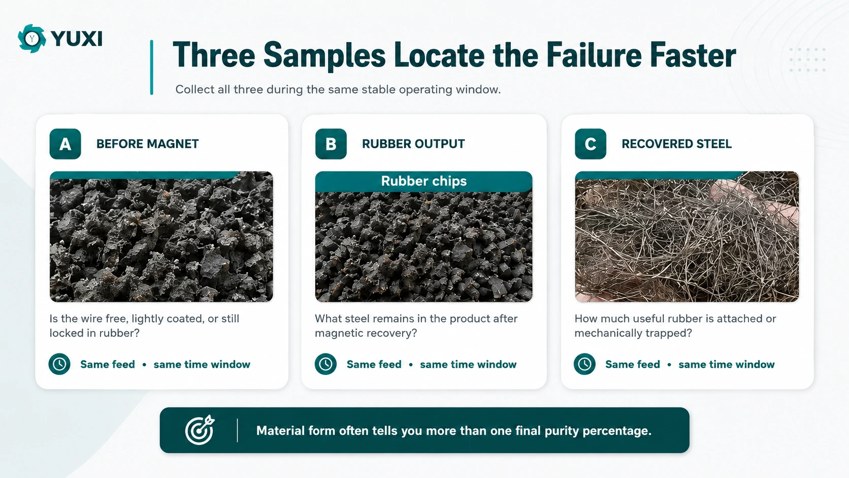
While collecting the samples, photograph the belt profile immediately before the magnet. Watch the actual capture point: does visibly free wire lift or divert cleanly, or does it remain buried? Follow the captured steel to the discharge and check for wrapping, bridging or material sticking to nearby structure. Then compare the rubber and steel outputs.
| Observed pattern | What it means | First direction |
|---|---|---|
| Sample A contains thick rubber-steel composites | Steel is not sufficiently liberated before magnetic recovery | Inspect upstream cutter/screen condition and liberation |
| Sample A contains free wire; Sample B also contains free wire | Recoverable steel is being missed | Inspect working distance, peak burden, speed, distribution and installation |
| Sample C contains large rubber pieces | Rubber is leaving with the captured steel | Improve liberation or clean the steel fraction |
| Defects occur mainly during surges | Load profile changes the magnetic condition | Stabilize feed and burden profile |
| Wire sticks on frames/chutes | Discharge or surrounding ferrous structure is interfering | Review discharge geometry and ferrous-free zone |
| Performance declines after normal accumulation develops | Buildup or mechanical condition is changing the stage | Inspect separator belt/cover, wire buildup and chutes before retuning |
If your plant uses a mass-based internal check, record the sample mass. If it uses a repeatable visual/count-based method, use that consistently instead. The purpose here is not to create a universal laboratory purity test; it is to compare like-for-like runs and locate the failing stage.
Balance Steel Removal Against Rubber Loss
A magnetic stage produces two output streams, so both should be judged. Very clean rubber does not automatically mean an efficient process if large amounts of good rubber leave with the recovered wire.
Use a repeatable internal trend for both sides: residual free-wire defects in the rubber and rubber carryover in the recovered steel. After an adjustment, one number improving while the other worsens may mean the plant is trading rubber yield for steel removal rather than improving the overall separation.
If rubber remains trapped in the recovered steel, more magnetic force is not automatically the answer. The wire may need better upstream liberation or a dedicated cleaning/reclaim step. Conversely, free steel consistently missed in the rubber points toward magnetic capture, presentation or installation.
A later magnetic stage is justified only when the remaining contamination becomes a genuinely different duty, such as small residual ferrous pieces in finer rubber. Material that continues into a rubber granulation and fiber removal system will have a different downstream size and contamination target. Textile fiber is a non-ferrous, non-magnetic impurity in this process, so a magnetic separator cannot remove it; fiber needs its own downstream separation stage.
Commission and Requalify the Stage in the Same Order
Use a fixed sequence during initial commissioning and after a meaningful change such as separator-height adjustment, conveyor-speed change, major upstream cutter/screen service, or magnetic/conveyor maintenance.
- stabilize upstream feed and burden profile;
- inspect Sample A to confirm liberation;
- confirm working distance and physical clearance;
- inspect idlers, frames, skirts and steel-discharge geometry;
- check separator belt/cover condition and wire buildup;
- compare Samples B and C;
- change one major variable if needed;
- repeat the same sampling and observation routine.
Hold the initial product after a major change until a quick verification shows that the stage has returned to its expected condition. Do not prescribe a universal test duration; the run only needs to be long enough to represent normal burden, material flow and the accumulation that normally occurs in your process.
The 3T/H waste tire recycling machine is useful as a YUXI line-level reference because it shows why this matters: the magnet receives material shaped by upstream reduction, conveyors and transfer points. It should not be used to invent a universal magnetic setting.
Move From Troubleshooting to Equipment Selection Only When the Evidence Supports It
If the existing stage is mechanically sound, steel is sufficiently liberated, feed presentation is stable and the magnetic stage still cannot meet the changed throughput or product requirement, the problem has moved from troubleshooting into equipment specification.
The broader tire steel wire separator specification guide covers that buying step. Before going there, keep the evidence from this diagnostic process: Sample A, Sample B, Sample C, belt profile, separator position and steel-discharge condition.
For a steel-recovery problem, send photos of material before the magnet, the rubber output, recovered steel, conveyor loading and the separator installation. Those views help identify whether the limit is liberation, magnetic capture, surrounding structure or wire discharge.